
| LINKMED®
Interface Tutorial: Creating Mapper Interface Template |
By default the first HL7 segments fields selected for the interface template will be displayed at the work area
(Figure 2).
The following is the HL7 MSH message segment of the input file received:
Input MSH Segment:
MSH|^~\@|PMS|LPI|RMS||200804151006||ADT^A08|CHPFQP02|P|2.3|
This is your first HL7 segment that you need to work on to extract contents from its segment fields.
Select the following MSH "Segment fields" that contains value by clicking the [Check Box] on the left:
3, 4, 5, 7, 9_1, 9_2, 10, 11, 12 (Figure 2).

Figure 2
Input
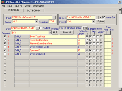
EVN Segment
EVN|A08|20020151006|20080410||FERGUJ^^^^^^^^^^^^^^
Next
click on the Down Arrow in the LINKMED® Mapper "
Segment" column and
select the EVN segment to bring up EVN segment fields.
Select the following EVN Segment fields:
1, 2, 3, 5 (Figure 3)

Figure 3
Input
PID Segment:
PID|0001||00081067^^^^^||DOE^JANE^A^^^^||19410602|F||1|123
ANY STREET^^ANYCITY^CA^935350000^^^^^||(123)456-7890^PRN^PH^^^661^9423708^^|||M|PRO|3000026959^^^^^|140323473
Next click on the Down Arrow in the LINKMED® Mapper " Segment"
column and select the PID segment to bring up the PID segment fields.
Select the following PID Segments Fields : 1,
3_1, 5_1, 5_2, 5_3, 7, 8, 10, 11_1, 11_3, 11_4, 11_5, 13_1, 13_2,
13_3, 13_6, 16, 17, 18_1, 19 (figure
4)

Figure
4
Input PV1 Segment:
PV1|0001|O||R|||005041^BARSTIS^JOHN^^^^^^^^^^^^|||RAD||||OP|||005041^BARSTIS^
JOHN^^^^^^^^^^^^|OP|003000026959^^^^^|H^200804100852|||||||||||||||||||OUTPATIENT|||||200804100852
Next click on the Down
Arrow in the LINKMED® Mapper " Segment"
column and select the PV1 segment to bring up the PV1segment fields.
Select the following PV1 Segment Fields: 1,
2, 4, 7_1, 7_2, &_3, 7_4, 10, 14, 17_1, 17_2, 17_3, 17_4, 18,
19_1, 20_1, 20_2, 39, 44 ( Figure
5)
1. Copy the HL7 Input file from the previous page to the LINKMED® OrderR folder,
2-Then using Windows command prompt call the LINKMED® Interface Engine to do your data transformation.
Example: c:\LINKMED\LINKCFG\LTUP.exe c:\LINKMED\LINKCFG\OrderLNKMPR Where c:\LINKMED\LINKCFG\LTUP.exe is the location of your installed LINKMED® Interface Engine (LTUP.EXE) and c:\LINKMED\LINKCFG\OrderLNK.MPR is the saved location of your Dynamic Mapper template file.
3- Check the OrderS folder for your XML output file.
Tip: Use Internet browser to validate your XML file output .
4. Download the complete example of this tutorial by clicking on the link below
|
|